
This post is also available in:
 Deutsch (German)
![]()
The performance of subwoofers can be unpredictable due to the nonlinear distortion produced by the subwoofer itself, especially under high-power conditions. CODA subwoofers have been designed to overcome this problem. The transducers in CODA’s sensor controlled low frequency elements contain an integrated velocity sensor that measures LF diaphragm movement in real time and compares it with the input audio signal. This proprietary sensor controlled technology is a self-optimising, closed feedback loop that precisely determines how much power the driver needs to accurately reproduce the original audio signal. Any distortion produced by the driver or the enclosure is instantly corrected.
The result is a line of well-behaved, high-fidelity, high powered CODA subwoofers that allow the system designer to approach low frequency reinforcement with the same detail, sophistication, and confidence as the rest of the audio spectrum.
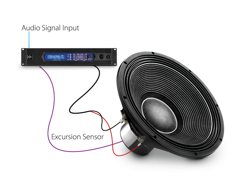
CODA sensor-controlled low-frequency element
HISTORY
Although modern pro audio subwoofers are almost all port or horn loaded, the idea of feedback control in loudspeakers is not new. The first patent was applied for in 1933 by Smythe and in the early 70’s Philips developed a speaker system called Motional Feedback (MFB) which was a feedback system for HiFi woofers based on a piezo acceleration sensor. For different reasons this technology did not succeed in the HiFi market. Today some High-end HiFi companies use the MFB technology in their products (Linn, SilberSand etc). Because of technical limitations especially at high power, the MFB technology was not suitable and has never been used in ProAudio.
The main difference between MFB and the CODA Audio sensor controlled technology is that while the MFB measure acceleration using a piezo sensor, CODA Audio utilises a patent pending electro-dynamical sensor, measuring the velocity of the voice coil offering the following advantages:
The piezo accelerometer is less precise especially at high excursion producing high amounts of distortion.
Loudspeakers produce variable magnetic AC-fields depending on the position of the voice coil which is very strong in high power, high excursion pro audio drivers. The external noise sources disturb the functionality of the piezo sensor. The CODA Audio electro-dynamical sensor measures the velocity of the voice coil with a 0.1 % tolerance at 60 mm of travel. It is shielded against external noise sources and accurate even at extreme high levels.
The goal is to use a negative feedback loop to control and stabilise the loudspeaker. If the measurement sensor is not exact or the measurement is disturbed, a positive feedback will occur which will add distortion. This happens especially at high power levels when the measurement source is not exact such as piezo accelerometers.
PROCESSING
Conventional loudspeakers need external processing to optimise their frequency response. The minimum processing for any port or horn loaded subwoofer is:
High pass filter (HPF), Low pass filter (LPF) and one or more parametric equalizer.
While the LPF is used to implement the subwoofer to the main system the HPF is used to protect the driver from over excursion and the EQ is needed to compensate for the lower efficiency at very low frequencies.
The processing increases the group delay and alters the impulse response of the system.
The CODA Audio sensor controlled subwoofer does not need any external processing (except LPF to implement it to the main system). It is a closed loop and therefore self optimising system in which the driver confirms accurately the power it needs to reproduce the original audio signal.
MEASUREMENTS
The SC8 sensor controlled subwoofer was measured 5cm from the cabinet to avoid room reflections. Only the front 2 x 18” speakers were activated, the rear 2 x18” were switched off to minimise room influences. No processing was applied except LPF 90Hz 24dB Link/Riley.
The conventional port loaded subwoofer is a high performance, large pro audio 2 x 18” subwoofer tuned at 32Hz and is measured 5cm from the port to avoid room reflections. Such a system is near the maximum of what can be achieve from conventional port loaded pro audio subwoofer. Typical processing was applied: HPF30Hz/24dB-But, LPF90Hz/24dB-Link/Riley PEQ35Hz+8dB. The frequency response curve shows only the lowest frequency range which is performed by the port.
Frequency response
Fig. 8.1 Sensor controlled subwoofer incl. LPF 90HZ 24dB Link/Riley Frequency response measures 5 cm from the loudspeaker
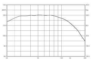
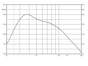
Fig. 8.2 Conventional port loaded subwoofer including processing Frequency response measured 5 cm from the loudspeaker port
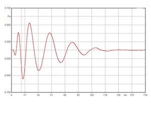
Impulse response
Fig. 9.1 Sensor controlled subwoofer incl. LPF 90Hz 24dB Link/Riley Impulse response measured 5 cm from the loudspeaker
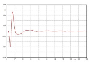
Fig. 9.2 Conventional port loaded subwoofer including processing Impulse response measured 5 cm from the lodspeaker port
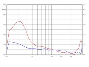
Group delay
Fig. 10.1 Sensor controlled subwoofer incl. LPF 90Hz 24 dB Link/Riley Group delay measured 5 cm from the loudspeaker
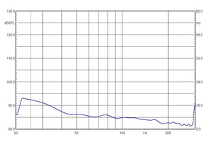
Fig. 10.2 Sensor controlled subwoofer vs. conventional port loaded woofer Group delay measured 5 cm from the loudspeaker port
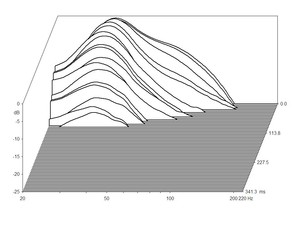
Waterfall
Fig. 11.1 Sensor controlled subwoofer incl. LPF 90Hz 24 dB Link/Riley Waterfall measured 5 cm from the loudspeaker
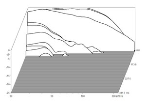
Note: It is difficult to measure low-frequency response of a speaker (even in an anechoic chamber), because of reflections from the environment. The SC8 waterfall measurement shows a small amount of reflections from the room at the 20 Hz – 40 Hz range.
Fig. 11.2 Sensor controlled subwoofer vs. conventional port loaded woofer Waterfall measured 5 cm from the loudspeaker port
INTERPRETATION OF THE MEASUREMENTS
It can be seen that the feedback loop controlled subwoofer has clear advantages over conventional amplifier / subwoofer solutions.
Frequency response
The sensor controlled technology does not have a cut off frequency. While the comparator is set to optimise the system response down to 25Hz (-3dB) / 20Hz (-6dB) (Fig.8.1) it can be easily adjust for flat response down to 10Hz or even lower if needed.
The conventional port loaded cabinet is a large pro audio 2 x 18” system tuned at 32Hz and is measured 5cm from the port to avoid room reflections. Typical processing was applied: HPF30Hz/24dB-But, LPF90Hz/24dB-Link/Riley PEQ35Hz+8dB. The frequency response curve shows only the lowest range which is performed by the port (Fig. 8.2). The frequency range is generally limited by the tuning frequency of the port which is the cut off frequency of such systems. Similar to horn loaded systems, port loaded subwoofers become extremely large if extended low frequency response is required. While at 36Hz both systems have the same output, the SC8 has 12dB more output at 25Hz and 23dB more output at 20Hz than a conventional system.
Impulse response
The impulse response describes the reaction of the system as a function of time. The sensor controlled system (Fig. 9.1) provides perfect impulse response while the conventional system shows increased group delay and altered impulse response caused by delayed sounds from the port (result of resonance) and the audio processing (Fig. 9.2). Such impulse response is very typical of port or horn loaded systems. The SC8 subwoofer provides very controlled impulse response assuring pure sound reproduction.
Group Delay
The sensor controlled system (Fig. 10.1) has near zero group delay in the range 42Hz- 100Hz. Under 42Hz the group delay increases slightly to 8ms@34Hz and reaches its maximum of 11ms@25Hz. In fact the sensor controlled system produces the whole spectrum acoustically in the same time, because such group delay is below the limit of our perception abilities.
The conventional subwoofer (Fig. 10.2 – Red line) provides increased group delay of 44ms @34Hz. If a fast sequence of transients arises the results can be blurred with imprecise sound. With the sensor controlled subwoofer, the transients are produced with the same time liaison as the input audio signal. This means that a fast sequence of transients will be clearly audible.
Waterfall
Even if the SC8 waterfall measurement (Fig. 11.1) shows a small amount of reflections from the room in the 20Hz-40Hz range it repeats what we have seen already in the impulse response – very fast and clean response ensuring homogeneity and precision of sound reproduction.
The conventional port loaded subwoofer (Fig. 11.2) provides the typical long resonance around the tuning frequency of the cabinet and the tendency to accentuate noise/interference around the given resonance.
Conclusion
While conventional subwoofer designs are well known from years of practice, to work well enough, the sensor controlled subwoofer technology allows a vital new step forward to be taken towards a truly complete and coherent speaker system set-up, providing extended low range with flat frequency and phase response for perfect reproduction of music with exceptional accuracy and definition.